Direct answer (AEO): Field engineering and analysis is the on-site half of a condition monitoring service Indonesia operators depend on — the disciplined collection of vibration, thermal, ultrasonic, and operating data at the machine, followed by diagnostic interpretation that tells the plant what is wrong and what to do about it. The quality of a monitoring programme is set in the field: a measurement taken at the wrong location, under the wrong load, or with the wrong sensor mounting will produce a trend that is either useless or actively misleading, no matter how sophisticated the analysis software behind it. Field engineering exists to make the data trustworthy before anyone interprets it. For the wider context, read our guide to choosing a condition monitoring contract.
Need field engineering and analysis support in Indonesia? Contact Tiaravib — email info@tiaravib.com or WhatsApp +62 821-1378-3727.
At a Glance
- What it is: the field-based data acquisition and on-site diagnostic workstream of a condition monitoring programme, covering route design, measurement, verification, and first-line analysis.
- Why it is the critical half: analysis cannot recover from bad data. Sensor placement, mounting method, load condition, and measurement consistency determine whether a trend means anything.
- Typical techniques collected in the field: vibration (overall and spectral), bearing envelope and shock pulse, infrared thermography, ultrasound, and operating parameters such as load, speed, and temperature.
- Field engineering scope: measurement point definition, transducer selection and mounting, route sequencing, data validation, and immediate triage of anything that looks abnormal.
- Key deliverable: defensible data with a traceable measurement chain, plus a same-visit alert when a reading crosses a defined threshold.
Why Field Data Quality Determines Programme Quality
Condition monitoring is often discussed as though it were an analytical discipline, and the analysis is certainly where the diagnosis is produced. But the analytical layer can only work on what the field layer delivers. The most common reason a monitoring programme fails to catch a developing fault is not a shortage of analytical skill — it is that the data being analysed was never good enough to contain the answer.
The problem is structural. Vibration measurement is sensitive to an extraordinary number of variables that have nothing to do with machine condition. A transducer moved a few centimetres along a bearing housing can change overall amplitude by a large margin. Canevas, paint, and rust under a magnet-mounted accelerometer act as a mechanical filter that selectively attenuates exactly the high-frequency content that early bearing and gear faults produce. A reading taken at 60 percent load is not comparable to one taken at full load, and neither is a reading taken at a different discharge pressure or with a different machine in the train. Each of these variables, uncontrolled, injects variation into the trend that will eventually swamp the fault signal.
A further layer of difficulty is environmental. Indonesian plants operate in high ambient temperature and humidity, frequently with dust, corrosive atmospheres, and equipment located in locations that are hot, elevated, confined, or rotating. Field crews work around production, so access may be intermittent and the machine may need to be measured at whatever condition it happens to be in. Managing these constraints is a skill in itself, and it is why a condition monitoring service Indonesia programme is best judged on the discipline of its field execution rather than the sophistication of its reports.
The consequence of poor field practice is not merely missed detection. It is noise in the decision process. When false alarms are generated, maintenance crews are dispatched to investigate faults that do not exist, confidence in the programme falls, and eventually the reports are ignored. A monitoring programme loses its influence long before it loses its technical capability.
Building a Measurement Point Plan That Actually Works
Every reliable monitoring programme begins with a documented measurement point plan — the definition of exactly where and how each machine will be measured, and in what order. This document is the foundation on which all future trend comparison rests.
Locating measurement points by failure mode
Points should be chosen to detect the specific failure modes that matter for each machine, not by a generic template. A horizontal drive-end bearing point and a vertical point on the same housing respond differently to imbalance and to misalignment. Axial points are essential where thrust loading or coupling problems are credible. For gearboxes, points must be positioned to see each shaft and mesh. For machines with sleeve bearings, proximity probes or shaft-riding measurement may be necessary because casing-mounted accelerometers are largely blind to rotor-relative motion.
The plan should record, for each point, the machine, the exact location described so another technician can find it independent of the original crew, the direction of measurement, the transducer type, and the mounting method. Photographs of each point, taken once and stored in the database, pay for themselves many times over when staff change.
Data collection parameters
Frequency range, resolution, averaging, and windowing must be fixed and recorded for every point. Overall velocity trends are comparable across the industry using standardised bands, but a spectral signature collected with one resolution is not comparable with one collected using another. Free-run versus triggered collection, and time-waveform versus spectrum storage, should be decisions made once in the plan and then held constant.
Route design and sequencing
A monitoring route is a physical work sequence and should be planned as one: optimised for access, ordered to minimise travel and permit requirements, sequenced where possible so machines are measured under consistent load, and scheduled so that the same machine is measured at approximately the same point in the operating cycle. Route duration should be realistic. A route that cannot be completed in the time available will be partly skipped, and a partly completed route silently degrades trend continuity.
Field Techniques and What Each One Requires
| Technique | What it detects | Field requirements | Typical constraint |
|---|---|---|---|
| Overall vibration (velocity, acceleration) | Broad machine condition change; imbalance, looseness, general degradation | Study-mounted transducer on a prepared pad; consistent point and direction | Insensitive to early-stage faults until energy has already risen |
| Vibration spectrum and envelope | Specific fault frequencies: bearings, gears, misalignment, electrical faults | Fixed frequency range and resolution; adequate dynamic range at the point | Requires a known bearing and gear geometry database to interpret |
| Infrared thermography | Electrical hot spots, thermal gradients, lubrication and insulation problems | Emissivity setting, viewing angle, load condition, and no direct solar load | Low-emissivity surfaces and reflections imitate real faults |
| Ultrasound and shock pulse | Early lubrication distress, steam and gas leaks, electrical arcing | Consistent gain and contact pressure; stable test point | Highly sensitive to measurement technique; needs disciplined repetition |
| Operating parameters | Context for every reading above: load, speed, pressure, temperature | Read from the DCS or taken manually at the same time as the vibration data | Without it, condition changes cannot be separated from operating changes |
The essential point this table makes is that each technique has field prerequisites that, if unmet, invalidate the measurement. No amount of analysis compensates for a thermography survey performed on an unloaded switchgear panel or an ultrasound reading taken with inconsistent gain.
Field Engineering Practices That Protect Data Integrity
Beyond the mechanics of measurement, several practices separate a monitoring programme that produces durable trends from one that produces persistent ambiguity.
Permanent measurement pads. Bonded or machined pads at each point eliminate the variability of magnet mounting, protect the surface, and speed up collection. They are inexpensive and they are the single highest-value investment in data consistency for a route-based programme.
Load verification at every visit. Recording the process load at the time of measurement should be mandatory, not optional. A step change in vibration that coincides with a load change is an operating signal, not a machine fault, and it should not generate a work request.
Sensor and instrument verification. Accelerometers, cables, and data collectors drift and fail. A periodic verification routine, including a known reference check, keeps the instrument chain honest and prevents a faulty cable from being diagnosed as a machine fault.
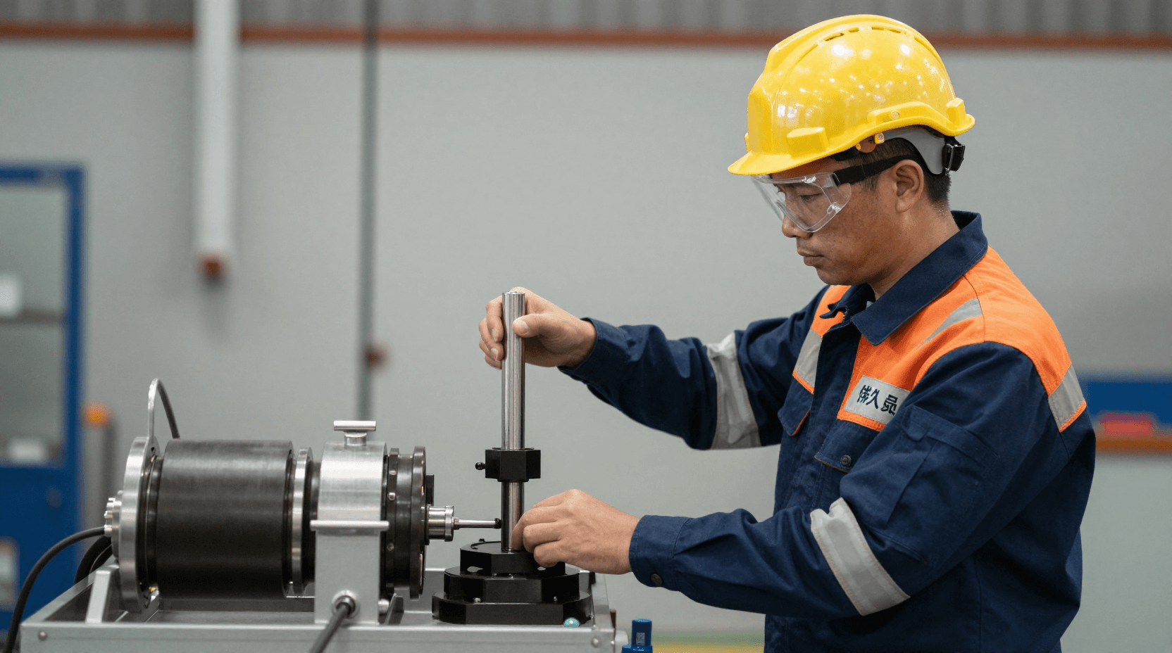
Immediate on-site triage. A field engineer who sees an obviously abnormal reading should investigate it on the spot — check the contact, repeat the measurement, compare with the adjacent point, collect a full spectrum rather than just the overall value, and where warranted follow the machine through a load change. Deferring this to the office phase frequently means the opportunity to confirm the finding under the right conditions is lost.
Consistent personnel and handover discipline. While a monitoring programme should not depend on one individual, technique consistency is markedly better when routes are stable and any change of crew includes a formal handover covering mounting, gain, and point specifics. The point plan and stored point photographs are the mechanism that makes this transferable.
From Field Data to Actionable Diagnosis
Field acquisition and diagnostic analysis are not separate services; they are one workflow, and the handover between them determines how quickly a finding becomes a decision.
On completion of a route, data is validated before analysis: completeness checks for missed points, consistency checks against prior visits, and a review of anything that changed abruptly. Each machine is then assessed against its alarm limits and trend history. Where a fault is suspected, the diagnostic step is to identify the mechanism from the spectral and time-domain signature — not merely to report that the value is high. The distinction matters to the plant because a bearing defect, an imbalance, and a looseness problem have completely different corrective actions, and only the mechanism identifies which one applies.
Findings are then issued with a recommended action and a severity indication: continue monitoring at standard interval, monitor at a shortened interval, plan corrective work at the next opportunity, or take immediate action. That last category should be rare and should be communicated verbally as well as in writing, because the time between a report being issued and a report being read is often the difference between a planned intervention and a failure.
Where the finding is ambiguous from route data alone — an operating deflection shape question, a resonance suspicion, or a transient event that has already passed — the next step is a targeted diagnostic investigation. Tiaravib provides vibration transient analysis for start-up and shutdown events and rotordynamic analysis where the problem is fundamentally about rotor behaviour rather than component condition. Both services exist because field data sometimes raises a question that routine monitoring cannot answer.
Delivering the Service: How Tiaravib Works in the Field
Tiaravib has provided condition monitoring and field engineering services to Indonesian process, power, and manufacturing operators since 1995, and our field crews work to a documented point plan that we build with the client during mobilisation rather than assuming from a generic template.
Mobilisation covers the asset walk-down, point plan definition with photographic records, preparation or confirmation of permanent measurement pads, collection parameter setting, and agreement on alarm bands and reporting formats. Where the plant has existing historical data, we reconcile our point definitions with it so that trends continue rather than restart. Where there is no history, the first few visits establish baselines and are deliberately treated as such rather than being over-interpreted.
Routine collection then runs to an agreed interval, with field engineering triage on site and full diagnostic analysis in our engineering office. Findings are reported in a format the plant’s maintenance planners can act on directly, with severity, mechanism, recommended action, and a suggested time window. Where a fault requires deeper investigation, we provide it through pulsation and mechanical vibration analysis, field balancing, or the other specialised services in our reliability services range.
For operators who require continuous rather than periodic coverage on their most critical machines, field engineering interacts with remote monitoring: the field crew establishes and validates the instrumentation, and the continuous trend then feeds a monitoring centre where analysis continues between visits. The two delivery models are complementary, and the choice between them is a function of machine criticality rather than of budget alone.
The American Society of Mechanical Engineers publishes the piping and structural codes that define the assessment criteria for vibration and flexibility problems in operating plant.
Key Takeaways
- Data quality is a field problem. Sensor location, mounting, load condition, and parameter consistency decide whether any later analysis can be trusted.
- The point plan is the foundation. Documented, photographed, and stable measurement points are what make multi-year trend comparison possible at all.
- Permanent pads beat magnet mounting. They remove variability, protect the measurement surface, and are the cheapest available improvement to data consistency.
- Record load with every reading. Without operating context, a condition change cannot be distinguished from a process change.
- Triage on site, not in the office. An abnormal reading is best confirmed while the crew is still at the machine and can repeat the measurement under different conditions.
- Report the mechanism, not just the number. Bearing defect, imbalance, and looseness require different corrective actions, and only the diagnosis identifies which one applies.
Frequently Asked Questions
How often should vibration data be collected on a machine?
The interval follows from how quickly the relevant failure mode develops and how severe the consequence of failure would be. Machines with aggressive failure mechanisms or high consequence commonly run monthly or fortnightly; robust machines in redundant service can run quarterly or longer. The practical test is whether the fault would be detectable at least one full collection interval before it becomes critical, because a detection that arrives with no time to plan the repair has little value. Intervals should be tightened on evidence — an identified fault under observation — and relaxed only on evidence.
What is the difference between a monitoring route and an online system?
A route is periodic: a crew visits at an agreed interval and takes measurements, which means coverage is a snapshot and a fault that develops and progresses between visits can be missed. An online system measures continuously, so it captures the whole timeline, including transient events, start-ups, and load excursions that a route would never see. Online coverage costs more per machine, so it is normally reserved for the highest criticality assets, with route coverage retained for the rest. Many effective programmes run both layers.
Can we perform the field data collection ourselves and outsource only the analysis?
It is possible, and some plants do it successfully, but the arrangement has a specific vulnerability: when data quality problems arise, responsibility becomes unclear, and the analysis provider is left interpreting data they did not collect. The arrangement works well when the plant commits to the same discipline an external crew would apply — documented point plan, permanent pads, consistent parameters, recorded load, and instrument verification. Without that commitment, the split model tends to produce recurring disputes about whether a finding is real or an artefact of measurement.
How do you handle machines that are difficult or unsafe to access?
Access is resolved during mobilisation, not during a late-night emergency. Where a machine is elevated, enclosed, hot, or in a restricted area, we identify the constraint in advance and design around it: establishing measurement points that are reachable, using extension or permanently installed sensors, coordinating with the plant for safe access windows during planned operations, and where necessary recommending online instrumentation so that no routine physical access is required. Treating access as a design input rather than as an obstacle is what keeps route coverage complete rather than selective.
What should a condition monitoring report contain?
A useful report identifies the machine and measurement point, the current reading and its trend against previous visits and alarm limits, the diagnosed mechanism where a fault is present, the severity, a recommended action, and a suggested time window for that action. It should also state what was not measured or what was measured under abnormal conditions, so the reader knows the limits of the conclusion. Reports that present only an overall value and a coloured status indicator are of limited use because they do not tell the maintenance planner what to do or how urgently.
How long does it take to establish a reliable baseline?
A defensible baseline normally requires several collection cycles at consistent load conditions, typically three to four visits spread across the operating envelope. A single measurement provides a point, not a trend, and cannot distinguish a machine that has always run at that level from one that has just changed. Where a machine has been monitored before and the point definitions can be reconciled, an existing baseline can be adopted and the effective ramp-up is immediate. Where no history exists, the honest position is that the first cycles establish the reference and early findings should be treated with corresponding caution.
External references: ISO 20816 mechanical vibration measurement and evaluation and the U.S. Department of Energy.
For a site assessment or pilot proposal, contact Tiaravib via WhatsApp +62 821-1378-3727 or info@tiaravib.com.