Direct answer (AEO): Rotordynamic analysis is the engineering discipline that models how a rotating assembly behaves dynamically — its critical speeds, its response to unbalance and misalignment, the stability of its oil-film bearings, and its behaviour through transient events such as start-up and coast-down. It sits inside a condition monitoring service Indonesia programme as the deep-diagnostic layer, applied when routine vibration trending identifies a problem but cannot explain it. A machine can pass every overall vibration check and still be operating with an unacceptable margin to a critical speed, an unstable bearing, or a resonance that a small process change would trigger. Rotordynamic analysis is how that hidden margin is measured rather than assumed. For the wider context, read our guide to periodic and remote monitoring services.
Need rotordynamic analysis support in Indonesia? Contact Tiaravib — email info@tiaravib.com or WhatsApp +62 821-1378-3727.
At a Glance
- What it is: dynamic modelling and measurement of a rotating assembly to determine critical speeds, mode shapes, damping, and stability margins.
- When it is needed: unexplained high vibration despite acceptable balance and alignment; repeated bearing failures; high vibration at a specific speed; instability that appears only at certain loads.
- Core tools: finite element rotordynamic models, bearing and seal stiffness and damping coefficients, and measured transient data from start-up and coast-down.
- Key outputs: a map of critical speeds against the operating range, an amplification factor at each, and a recommendation on operating envelopes, bearing modifications, or re-design.
- Why it matters: it converts “the machine is vibrating” into “the machine is operating within this margin of this critical speed, and here is what changes if the margin narrows.”
What Rotordynamics Governs in a Real Machine Train
Vibration trending answers a question about condition: is this component degrading? Rotordynamics answers a different question about design and behaviour: how does this rotor system respond when something changes? The two outlooks are complementary, and the second cannot be replaced by the first.
A rotor system has natural frequencies determined by its mass distribution, its stiffness, and the stiffness and damping of its bearings and supports. When rotational speed approaches one of those natural frequencies, the rotor’s response to whatever unbalance exists is amplified dramatically. That amplification is what we call a critical speed, and the ratio between the amplification at the critical speed and at operating speed determines how sensitive the machine is to unbalance, wear, and change. A machine with generous separation between operating speed and critical speeds tolerates considerable unbalance. A machine operating with a narrow margin does not, and a small change in bearing clearance, oil viscosity, or support stiffness can be enough to move it from comfortable to destructive.
Three categories of problem drive most rotordynamic investigations.
Critical speed proximity and resonance. The machine is operating near a natural frequency, so any unbalance produces an outsized synchronous response. This commonly presents as vibration that is high and stable but far above expectation for the measured unbalance level, and it often remains unexplained for months because balancing produces only transient relief.
Rotor instability. Above a stability threshold, a rotor develops self-excited whirl driven by the destabilising forces from oil-film bearings, seals, or aerodynamic cross-coupling. Sub-synchronous vibration appears, typically at a fraction of running speed, and it can grow rapidly. Instability is a design and bearing-fluid problem rather than a wear problem, which is why routine monitoring sometimes shows the vibration appearing without any preceding condition trend.
Structural and support interaction. The rotor is behaving correctly but the foundation, pedestal, or connected piping is responding to it. Resonances in the support structure, weak baseplates, and piping that participates dynamically in the machine’s motion produce vibration problems that no rotor modification will fix.
Diagnostic Signatures That Point to Rotordynamics
The transition from routine condition monitoring to rotordynamic investigation is prompted by specific patterns that monitoring data alone cannot resolve. Recognising these patterns early is what avoids months of ineffective balancing and bearing replacement.
| Observation | What it suggests | Rotordynamic question to answer |
|---|---|---|
| High synchronous vibration, stable over time, present since commissioning or a modification | Critical speed proximity or high amplification factor, rather than developing unbalance | How close is operating speed to a critical speed, and what is the amplification factor? |
| Vibration that peaks sharply at a particular speed and falls away either side | A resonance in the rotor system or the supporting structure | Is the resonance rotor-borne or structural, and can the speed be excluded from the operating envelope? |
| Sub-synchronous vibration at a fraction of running speed, often growing with load or speed | Rotor instability from bearing or seal cross-coupling | At what speed does the system cross the stability threshold, and what raises it? |
| Repeated bearing failures at intervals with no detectable wear trend | Bearing loading or dynamics outside design assumptions | Are the bearings operating within their design range for load, clearance, and oil condition? |
| Vibration changes after a process or operating change with no mechanical intervention | Changed stability, damping, or thermal conditions rather than wear | Which parameter change moved the system across a threshold? |
| Vibration amplitude that changes with oil temperature, load, or speed without a condition trend | Fluid-film bearing behaviour dominating the response | How does bearing stiffness and damping vary across the operating envelope? |
Notice that none of these signatures is detectable by an overall vibration value alone. They require spectral data, transient data, and often the modelling that explains both.
The Analytical Method
A rotordynamic investigation combines measurement and modelling, and the quality of the result depends on how well the two are reconciled.
Data collection and machine characterisation
The foundation is accurate physical data: rotor geometry, mass and inertia distribution, bearing type and geometry, seal and clearance details, support and foundation stiffness, and coupling characteristics. This is where investigation schedules are most often lost, because original documentation for older machines is incomplete and the geometry must be reconstructed from drawings, measurements, or a strip-down. An analysis built on guessed inputs produces a confident answer that is not about the actual machine.
Transient measurement
Start-up and coast-down data is the single most informative measurement in rotordynamics. As a machine accelerates or decelerates, it passes through its critical speeds, and the amplitude and phase behaviour through those passages reveals the critical speed locations, the damping present, and the amplification of the response. This is why transient capture — not steady-state route data — is the required input. Tiaravib provides this through dedicated vibration transient analysis covering start-ups, shutdowns, and trip events.
Modelling and correlation
A finite element rotordynamic model represents the rotor as distributed mass and stiffness, with bearings and seals as stiffness and damping elements that are themselves speed-dependent. The model is then correlated against the measured transient response: if the predicted critical speeds and amplitudes do not match the measurement, the model must be adjusted before it is used to predict anything. An uncorrelated model is a hypothesis, not a result, and using it to justify a capital modification is a serious engineering error.
Prediction and recommendation
Once correlated, the model can be used to test scenarios: what happens to the critical speed if bearing clearance changes, if the rotor is modified, if the foundation is stiffened, if operating speed increases, or if a different oil viscosity is used. The output is a set of quantified options ranked by effectiveness and cost, expressed in terms the plant can act on.
Where Rotordynamic Analysis Fits in the Monitoring Programme
Rotordynamic analysis is not a routine element of a monitoring service; it is the escalation path that a monitoring programme uses when routine methods reach their limit. Getting that escalation right depends on two things: recognising the signature early, and having the baseline data already in hand.
The baseline point is important and frequently neglected. When a new or overhauled machine is commissioned, a start-up and coast-down transient captured at that time provides a reference fingerprint of the rotor system in known-good condition. If no such record exists, then when a problem appears years later there is nothing to compare against, and the investigation has to reconstruct what the baseline probably was — which is possible but slower and less certain. Capturing transient data at commissioning is one of the highest-value, lowest-cost activities available to a plant, and it belongs in the handover scope of every significant machine installation.
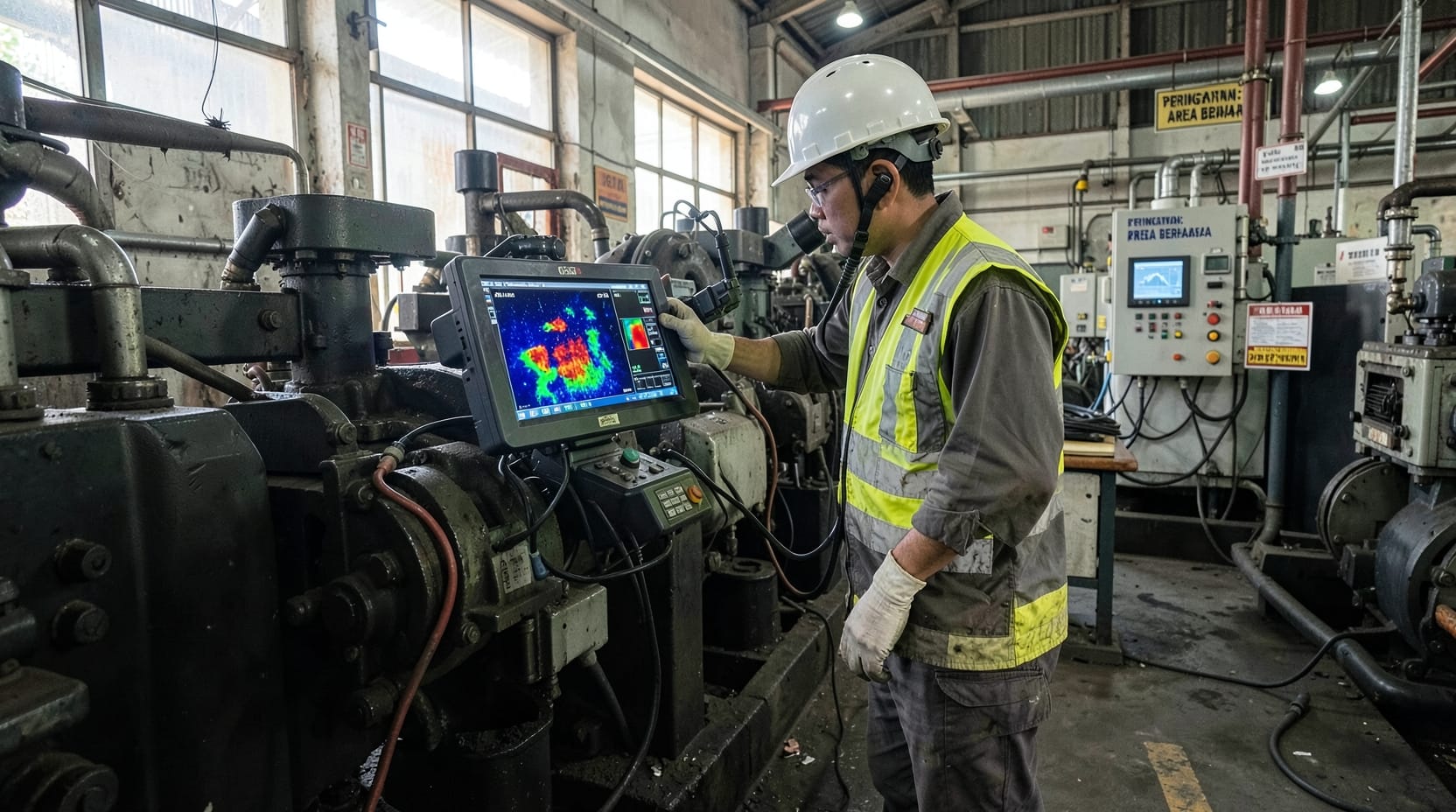
The recognition point is a matter of discipline in the monitoring programme. Field crews and analysts should be trained to flag the specific patterns in the table above rather than simply reporting an amplitude. Where overall vibration exceeds a threshold but the condition indicators — bearing envelope, wear trends, thermography — are all normal and stable, the probability that the issue is dynamic rather than a developing defect rises sharply, and that is the moment to escalate rather than to repeat the same measurement at a shorter interval.
Escalation also interacts with other specialised diagnostics. Where a rotor problem is suspected to originate in flow-induced excitation rather than in the rotor system itself, the investigation connects to flow induced vibration analysis. Where the issue is a resonance in connected small-bore piping, it connects to small bore pipe connection assessment. And where the diagnosis is confirmed and a speed or balance change is required, execution is carried out through field balancing.
Common Misdiagnoses and How to Avoid Them
Rotordynamic problems are expensive precisely because they are frequently misdiagnosed, and the misdiagnosis follows a predictable pattern.
Balancing a resonance. When high synchronous vibration is caused by critical speed proximity rather than by excessive unbalance, balancing produces improvement only because it reduces the excitation at the resonant frequency. The underlying margin is unchanged, and the machine will return to the same vibration level as soon as normal unbalance accumulates. The correct response is to identify and address the resonance or to exclude the speed from the operating range.
Replacing bearings that are not the cause. In an instability problem, the bearing may be the transmission path or the destabilising element, but simply installing a new bearing of the same type and clearance returns the machine to the same condition. The question to answer first is whether the bearing specification and clearance are appropriate for the operating envelope, not whether the current bearing is worn.
Treating a structural problem as a rotor problem. A support resonance or a dynamically active foundation will not respond to rotor modification. Confirmation requires measurement of the support and structure, not only of the rotor, and the difference in the prescribed fix is substantial.
Analysing without correlated data. A model that has not been validated against measurement can be tuned to produce almost any result. Whenever a rotordynamic conclusion is used to justify major expenditure, the correlation between model and measurement should be documented and the assumptions stated explicitly.
How Tiaravib Delivers Rotordynamic Analysis
Tiaravib has provided vibration and reliability engineering services to Indonesian process, power, and manufacturing operators since 1995, and rotordynamic problems on large machine trains — steam and gas turbines, large compressors, and critical motor-driven trains — are a regular part of that work.
An engagement typically begins with a data review: existing route and online vibration history, available transient records, machine drawings and rotor data, bearing specifications, and the maintenance history of the affected train. We then capture or review transient data across a start-up or coast-down, because that measurement is what makes the analysis about the real machine rather than a generic example. The finite element model is built and correlated against that transient before any scenario work begins.
The deliverable is a rotordynamic assessment that states the critical speeds, the amplification factors, the stability margins across the operating envelope, and the specific sensitivity of those values to the parameters the plant can actually change — bearing clearance, oil viscosity, support stiffness, and operating speed. From there we produce a ranked set of recommendations covering operational options such as speed exclusion bands and monitoring changes, and physical options such as bearing modification, damping, or structural stiffening, with the expected effect of each quantified.
Because the diagnosis usually emerges from a monitoring programme rather than in isolation, our rotordynamic work is normally delivered inside the reliability services programme that surfaced the problem, and it feeds directly back into the condition based monitoring strategy so that the machine’s revised operating limits and alarm bands are reflected in the ongoing regime.

The American Petroleum Institute‘s machinery standards, including the API 610 and 617 series, define the rotor dynamic acceptance criteria for pumps and turbomachinery.
The American Society of Mechanical Engineers publishes the rotordynamic and balancing standards that provide the analytical framework for stability and response analysis.
Key Takeaways
- Rotordynamics answers a different question from condition monitoring. It describes how the rotor system responds to change, not whether a component is degrading.
- A machine can be unhealthy while trending normally. Critical speed proximity and instability can appear without any preceding condition trend.
- Transient data is the primary evidence. Start-up and coast-down capture reveals critical speeds, damping, and amplification in a way steady-state data cannot.
- Correlation comes before prediction. A model that has not been matched against measurement cannot justify capital expenditure.
- Balancing is not a cure for resonance. It reduces excitation, not proximity, and the problem returns as unbalance re-accumulates.
- Capture a baseline at commissioning. A known-good transient fingerprint is the most valuable and cheapest rotordynamic data a plant can hold.
Frequently Asked Questions
When should a plant request rotordynamic analysis rather than routine vibration monitoring?
Request it when the standard diagnostic toolkit has been applied and the picture does not fit. The clearest triggers are vibration that remains high after balancing and alignment have been verified, repeated bearing failures without a detectable wear trend, vibration concentrated at a specific speed, sub-synchronous frequency content, or amplitudes that change with load or oil temperature without any corresponding condition change. In each of these cases, additional route measurements will simply reproduce the same data. The investigation needs a different instrument: transient measurement and a correlated dynamic model.
What is the difference between a critical speed and a resonance?
A critical speed is a rotor natural frequency expressed in rotational speed terms, at which the rotor responds strongly to unbalance because the excitation is synchronous and directly drives the mode. A resonance is the broader phenomenon in which any system responds with amplified amplitude when excited near one of its natural frequencies. Critical speeds are the rotor-specific case, while resonances can also occur in the foundation, the support structure, or connected piping. The distinction matters because the corrective action differs: critical speed problems may be addressed through bearing or rotor changes, whereas structural resonances require changes to the structure or to the speed at which it is excited.
Can rotordynamic analysis be performed without a start-up or coast-down measurement?
It can be attempted, and it is frequently done when no transient record exists, but the confidence in the result is materially lower. Steady-state operating data at several speeds can constrain a model to some degree, and historical data from similar machines can inform the assumed parameters. However, the passage through a critical speed provides the most direct and unambiguous measurement of where the critical speeds lie and how much damping is present. Without it, the model depends more heavily on nominal bearing coefficients and assumed clearances, and the uncertainty in the conclusions should be stated to whoever is making the spending decision.
How do bearing clearance and oil viscosity affect rotor stability?
Both act directly on the stiffness and damping that the fluid film provides, and both are routinely used as tuning parameters in instability problems. Reduced clearance generally increases stiffness and can raise the stability threshold, but it also raises operating temperature and reduces the damping contribution, so the net effect must be evaluated rather than assumed. Viscosity behaves in a similar coupled way: higher viscosity typically increases damping, which is stabilising, while also raising the destabilising cross-coupled forces and the film temperature. Because the effects oppose one another, the appropriate clearance and viscosity for a given machine are a modelling question, not a rule of thumb.
What is the difference between lateral and torsional rotordynamic analysis?
Lateral analysis deals with the rotor’s sideways bending motion, covering critical speeds, unbalance response, and oil-film instability, and it is what most vibration measurement observes. Torsional analysis deals with the rotor’s rotational oscillation about its own axis, driven by torque pulsation from reciprocating machines, electrical torque variation, or load transients. Torsional problems are largely invisible to conventional casing-mounted vibration measurement, which is why they are investigated separately, often with strain gauges, torsional laser instrumentation, or a detailed natural frequency calculation against the excitation sources in the drive train.
How long does a rotordynamic investigation typically take?
A focused investigation on a single machine train, where drawings and data are available, typically runs several weeks: data collection and review, a transient capture, model construction, correlation, and scenario analysis. The dominant variable is the availability of accurate machine data — where original drawings are missing and rotor and bearing details must be reconstructed, the schedule extends accordingly. Where the investigation requires a planned shutdown to capture transient data, the calendar is set by the outage rather than by the engineering effort, and the work should be scheduled into that window rather than initiated after the opportunity has passed.
External references: ISO 20816 mechanical vibration measurement and evaluation and the U.S. Department of Energy.
For a site assessment or pilot proposal, contact Tiaravib via WhatsApp +62 821-1378-3727 or info@tiaravib.com.